
If you’re designing a power supply, especially a high-voltage power supply, roads to failure must be considered. Creepage and clearance establish the minimum distance between conductive elements on PCBs and are critical factors in designing electrical components to prevent damage and ensure safety.
Maintaining proper insulation distances is crucial to avoid electrical arcing, which can occur when voltage or electrical potential builds up and jumps across a gap between conductors. When designing electrical components, engineers must ensure that the creepage and clearance distances meet specific standards based on the operating voltage and environmental conditions to prevent electrical breakdowns.
Let’s explore the importance of creepage and clearance in power supplies.
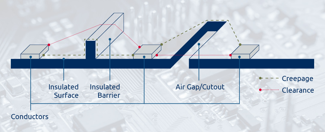
Both creepage and clearance describe the distance between conductive parts, though they each have slightly different meanings. Creepage refers to the spacing between conductive parts along an insulator surface, while clearance refers to the spacing between conductive parts through air. Though their definitions differ, creepage and clearance do share a few similarities. They both:
Though related, there are also notable differences between the two. Diving deeper into their definitions, creepage is the shortest distance from one conductor to another across an insulated surface, such as a PCB, component packaging, or wire insulation. Think of a liquid traveling along the surface, crawling or “creeping” from one conductive point to another. On the other hand, clearance is the shortest distance from one conductor to another through air. Think of throwing an object, like a football, to another object. Clearance is the space between them—or, in our case, between two conductive points.
When it comes to mitigating failure and avoiding an electrical arc, the approach to creepage and clearance also differs. To combat creepage, typically a small piece of the board is cut out (see the figure above). This physically increases the distance from one conductor to another along the surface of the PCB. Alternatively, a typical approach to combating clearance would be using an insulated barrier, like conformal coating. Both methods increase the spacing to counteract potential hazards.
In addition to voltage and the type of insulating materials used, differing environmental factors also affect creepage and clearance and should be considered when designing a power supply. Factors like pollution, humidity, and condensation impact creepage and the working voltage (Vrms). Working voltage is the ongoing voltage a power supply is designed to operate under. Air pressure (altitude) and temperature impact clearance and the transient voltage (Vpeak)—a sudden, brief spike or surge exceeding the working voltage. When considering the operating altitude, note that the higher the altitude, the greater the required clearance distance. As air density decreases, so does the dielectric strength, which reduces the insulating effect of air, making it easier for two conductors to arc. Environmental variable planning is crucial to avoiding electrical failure and unreliability in application-specific, military-grade power supplies.
If creepage and clearance are not managed properly, your system could experience intermittent failures. Failures usually result in an arc between conductors. This could put dangerous voltages on circuits not rated to handle that amount of voltage and could destroy sensitive circuitry. Or worse, spike voltages in places where human contact occurs, providing an unsafe environment for operators.
Failures caused by creepage and clearance violations can also prove to be difficult to troubleshoot and expensive to remedy. Failures can be caused by several variables, such as the age of the PCB, operating time, operating levels, and environmental changes. To remedy these failures typically means redesigning the board with higher clearances or finding a solution that would commonly require expensive material and excessive time to implement.
Another effect or byproduct of creepage and clearance is the size of the electronics. The greater the clearance requirement, the larger the components used or the number of components needed to address the specification. This conundrum increases the unusable space between conductors and enlarges the overall power supply design to accommodate this requirement, making trouble for any size requirement.
Meeting creepage and clearance standards can create issues with available volume and packaging. Depending on the environment, system engineers may have to account for the allocated volume for the power supply to be sufficient. This ensures a reliable design can be achieved.
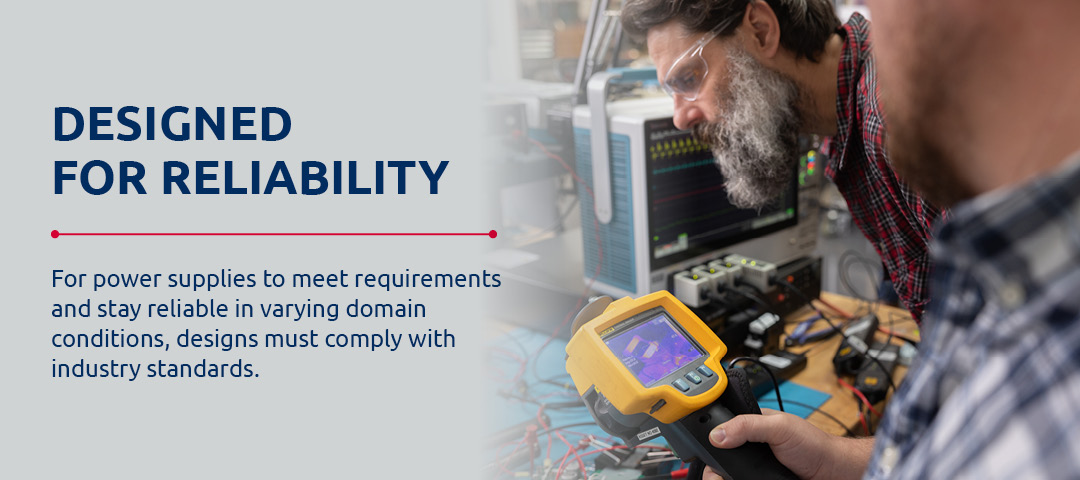
It’s no secret that military power supplies must perform under pressure in varying domains. For power supplies to meet requirements and be reliable in these conditions, designs must comply with industry standards. Some of these standards are:
In addition to the standards above, others may be required depending on application needs, such as MIL-STD-2000 (MIL-STD-108), MIL-HDBK-454B, and MIL-E-917. These military standards are for PCB design and outline creepage and clearance requirements.
Mitigating the risk of electrical malfunction is key. Adding to the measures mentioned earlier, oil mixtures are used in high-voltage applications for their ability to improve the dielectric constant in comparison to air or conformal coatings. This method improves thermal performance. Oil conducts heat away from the electronics and to the outer heatsink (enclosure) much more efficiently than natural convection or forced convection applications due to its higher cooling capacity.
At the PCB level, simple steps can be taken to remove excess risk, such as establishing PCB rules that provide adequate spacing depending on the application and operating environment. As mentioned, board cutouts can be used to increase creepage spacing. Selecting the proper package size of components can also be a critical step and could have an impact on the manufacturing of the power supply. At a system level, things like conformal coating and oil filling can increase the dielectric strength of the space between conductors.
“At ACT, we use a proprietary oil/gas mixture that inhibits potential arcing in high-voltage power supplies,” says Thomas D’Auria, Senior Design Engineer at ACT. “In conjunction with following the rules outlined in IPC-2221B, our team will design printed circuit boards with slots to create a physical gap between points that have a high potential difference to prevent voltage breakdown or arcing. Insulators are also used in our designs to create a barrier between any high-voltage potential and the chassis.”
The enclosure design can also be manipulated to mitigate environmental effects. A sealed enclosure could prevent foreign debris from entering the system and affecting the cleanliness of the board, avoiding any standoff voltage impacts.
It’s important to note that if a higher dielectric constant is not used for high-voltage applications, a corona discharge can occur. This phenomenon is the ionization of a neutral fluid surrounding a conductor, like air, when the conductor dielectric breaks down. Signs of a corona discharge are a faint yet visible blueish-purple glow, hissing sound, and potential radio interference.
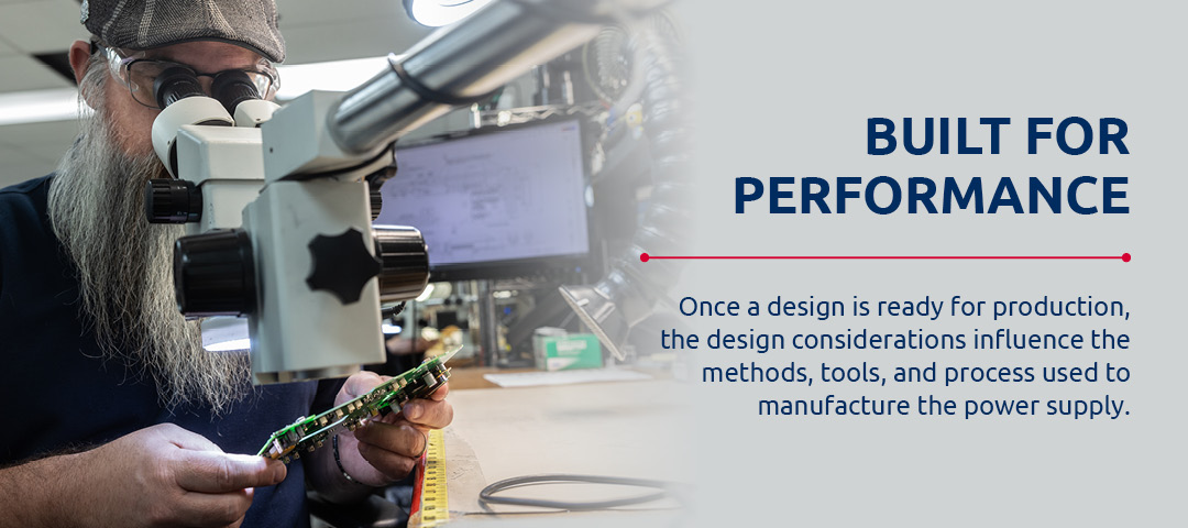
Creepage and clearance also impact the manufacturing process. Once a design is ready for production, the design considerations influence the methods, tools, and processes used to manufacture the power supply. Other factors include the type of materials used, material cost, and quality control.
Foreign object debris (FOD), such as flux residue, dust, excessive solder, wire clippings, metal shavings, component leads, and moisture can settle on the board, providing a conductive path between two conductors or decreasing the creepage distance and standoff voltage capability. PCBs should be thoroughly cleaned after all soldering processes and handled in a manner that precludes the introduction of FOD into the unit. PCBs also must be tested for ionic residues after cleaning to ensure that the cleaning process is stable and achieves the desired level of cleanliness. The impacts of these considerations are magnified in high-voltage applications.
The design process must consider, and accommodate for, a reasonable level of variability in the manufacturing process. Even with automated soldering processes, some degree of variability is permitted by IPC standards, such as the precise lead length of Plated Through Hole (PTH) components, the exact positioning of Surface Mount Technology (SMT) components on pads, and the amount of solder applied to each connection. Furthermore, the design process must also take steps to reduce complexity—and thus risk and cost—wherever possible. For instance, the use of insulating materials between non-common conductors in lieu of an air gap will allow for a higher density of circuitry within the unit. This allows the unit to retain a smaller form factor. However, the addition of insulators also represents an increase in complexity, risk, and cost. Designs should strive to be optimized to effectively balance cost and ease of manufacturing with performance and reliability.
At Advanced Conversion Technology (ACT), our engineering and manufacturing pros understand the need for sophisticated, precision-engineered power supplies that meet the particular requirements of military applications. We offer ruggedized and reliable AC-DC MIL-COTS and DC-DC MIL-COTS power supplies for off-the-shelf needs, custom power solutions, and build-to-print services.
Our vertically integrated facility allows us to address potential impacts like creepage and clearance while meeting your schedule. We have our quality system certified to AS9100D and ISO9001:2015 and are seriously committed to providing power solutions that perform and protect. So, whether you require a power supply that’s off the shelf or one that’s custom, we’re at the ready to partner with you in building a power supply you can depend on. Contact us today!
